


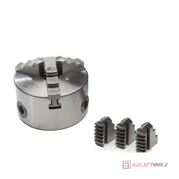
The 3 Jaw Hydraulic Chuck use dustproof patent structure can prevent the metal chips get into chuck inside.
The 3 Jaw Hydraulic Chuck is a type of clamping device used in CNC lathe machines for precision workholding. It features a three-jaw chuck design, which is capable of securely gripping cylindrical or round workpieces. The hydraulic mechanism enables smooth, controlled clamping force, making it highly effective for precision machining tasks, such as turning or milling.

|
MODEL / SPEC
|
Plunger
Stroke (mm) |
Jaw Stroke
[Diameter] (mm) |
Max.Speed
r.p.m(min-1) |
Max.Pull
Force kgf(kN) |
Max.Gripping
Force kgf (kN) |
Max Hydr.
Pressure kgf/cm2(MPa) |
Weight
(kg) |
Matching
Cylinder |
Gripping
Range |
|---|---|---|---|---|---|---|---|---|---|
|
CL-12DP
|
30
|
10.5
|
3200
|
4080(40)
|
15500(152)
|
29(2.8)
|
64.4
|
L1530(L1530RE)
|
ø18~ø304
|
|
CL-15DP
|
35
|
16
|
3000
|
8260(81)
|
25290(248)
|
32(3.1)
|
104.1
|
L2035(L2035RE)
|
ø68~ø381
|
|
CL-18DP
|
35
|
16
|
2700
|
8260(81)
|
25290(248)
|
32(3.1)
|
138.5
|
L2035(L2035RE)
|
ø100~ø450
|
|
CL-21DP
|
35
|
16
|
1900
|
8650(85)
|
27000(265)
|
33(3.2)
|
204.8
|
L2035(L2035RE)
|
ø80~ø530
|
|
CL-24DP
|
35
|
16
|
1700
|
8650(85)
|
27000(265)
|
33(3.2)
|
260
|
L2035(L2035RE)
|
ø155~ø610
|
|
CL-32DP
|
35
|
16
|
1100
|
8650(85)
|
27000(265)
|
33(3.2)
|
455.4
|
L2035(L2035RE)
|
ø155~ø800
|
|
CL-40DP
|
35
|
16
|
800
|
8650(85)
|
27000(265)
|
33(3.2)
|
--
|
L2035(L2035RE)
|
ø155~ø1000
|
|
MODEL / SPEC
|
Nose Of
Spindle |
A
|
B
|
C
(h6) |
D
|
E
|
E1
|
F
|
G
|
H
|
K
|
L
|
M
|
|---|---|---|---|---|---|---|---|---|---|---|---|---|---|
|
CL-12DP
|
A2-8
|
304
|
110
|
220
|
139.719
|
18
|
--
|
6
|
190
|
171.4
|
6-M16×2P
|
20
|
30
|
|
CL-15DP
|
A2-11
|
381
|
118
|
300
|
196.869
|
22
|
--
|
6
|
260
|
235
|
6-M20×2.5P
|
32
|
43
|
|
CL-18DP
|
A2-11
|
450
|
118
|
300
|
196.869
|
22
|
--
|
6
|
260
|
235
|
6-M20×2.5P
|
32
|
43
|
|
CL-21DP
|
A2-15(A2-11)
|
530
|
129
|
380
|
285.775
|
27
|
41
|
6
|
330.2
|
330.2
|
6-M24×3P
|
33
|
60
|
|
CL-24DP
|
A2-15(A2-11)
|
610
|
129
|
380
|
285.775
|
27
|
41
|
6
|
330.2
|
330.2
|
6-M24×3P
|
33
|
60
|
|
CL-32DP
|
A2-15(A2-11)
|
800
|
129
|
380
|
285.775
|
27
|
41
|
6
|
330.2
|
330.2
|
6-M24×3P
|
33
|
60
|
|
CL-40DP
|
A2-15(A2-11)
|
1000
|
129
|
380
|
285.775
|
27
|
41
|
6
|
330.2
|
330.2
|
6-M24×3P
|
33
|
60
|
|
MODEL / SPEC
|
N
max. |
N
min. |
O
max. |
O
min. |
P
max. |
P
min. |
Q
|
R
|
S
|
T
|
U
|
V
|
W
|
X
|
Y
|
|---|---|---|---|---|---|---|---|---|---|---|---|---|---|---|---|
|
CL-12DP
|
60.63
|
55.32
|
48.55
|
20.05
|
163
|
133
|
50
|
18
|
36
|
5
|
M20×2.5P
|
50
|
54
|
129
|
--
|
|
CL-15DP
|
69.05
|
60.97
|
58.05
|
40.05
|
104
|
69
|
62
|
25.5
|
55
|
7
|
M30×3.5P
|
60
|
68
|
165
|
--
|
|
CL-18DP
|
99.46
|
91.38
|
58.05
|
40.05
|
92
|
57
|
62
|
25.5
|
55
|
7
|
M30×3.5P
|
60
|
68
|
165
|
--
|
|
CL-21DP
|
80.49
|
72.41
|
101.8
|
41.8
|
96.95
|
61.95
|
65
|
25
|
55
|
7
|
M30×3.5P
|
60
|
75.5
|
180
|
235
|
|
CL-24DP
|
119.49
|
111.41
|
101.8
|
41.8
|
96.95
|
61.95
|
65
|
25
|
55
|
7
|
M30×3.5P
|
60
|
75.5
|
180
|
235
|
|
CL-32DP
|
119.49
|
111.39
|
197.8
|
41.8
|
97
|
61.95
|
65
|
25
|
55
|
7
|
M30×3.5P
|
60
|
75.5
|
180
|
235
|
|
CL-40DP
|
119.49
|
111.39
|
299.8
|
41.8
|
97
|
62
|
65
|
25
|
55
|
7
|
M30×3.5P
|
60
|
75.5
|
180
|
235
|


Get A Quote
Get A Free Consultation
Please feel free to get in touch using the form below.We shall reply within the following 24hrs.